音量指示器--Sound Level Indicator
This project uses an LM3915 bar-graph IC driving two sets of ten LEDs for a 30dB range. The circuit is unique because it has an additional range of 20dB provided by an automatic gain control to allow it to be very sensitive to low sound levels but it increases its range 20dB for loud sounds.

The LEDs are operating at 26mA each with the brightness control at maximum, which is very bright. The circuit has a switch to select the modes of operation: a moving dot of light, or a bar with a changing length.
My prototype has a little 9V Ni-Cad rechargeable battery in it to be portable and the battery is trickle-charged when the project is powered by a 9V AC-DC adapter.

Circuit Description
1) The electret microphone is powered by and has a load of R1 from an LM2931 5V low-dropout regulator.
2) The 1st opamp stage is an audio preamp with a gain of 101.
3) The 2nd opamp stage is a single-supply opamp which works fine with its inputs and output at ground and is used as a rectifier driver with a gain of 1.8. It is biased at ground. Since it is inverting, when its input swings negative, its output swings positive.
4) Three 2N3904 transistors are used as emitter-followers:
a) Q1 is inside the negative feedback loop of the 2nd opamp as a voltage reference for the other two transistors. Hopefully the transistors match each other.
b) Q2 emitter-follower transistor quickly charges C8 which discharges slower into R13 and is used as a peak detector.
c) Q3 transistor is the automatic gain control. It is also a peak detector but has slower charge and discharge times. It drives the comparators’ resistor ladder in the LM3915 to determine how sensitive it is. R15 from +5V is in a voltage divider with the ladder’s total resistance of about 25k and provides the top of the ladder with about +0.51V when there is a very low sound level detected. Loud sounds cause Q3 to drive the top of the ladder to 5.1V for reduced sensitivity.
5) The LM3915 regulates the current for the LEDs so they don’t need current-limiting resistors. In the bar mode with all LEDs lit then the LM3915 gets hot so the 10 ohm/1W resistor R16 shares the heat.

Options
1) You could use a switch to change the brightness instead of a pot, or leave it bright.
2) You could use an LM358 dual opamp (I tried it) but its output drops above 4Khz. The MC33172 is flat to 20kHz with this high gain.
3) You could add a 1uF to 2.2uF capacitor across R5 so the indicator responds only to bass or “the beat” of music. Then an LM358 dual opamp is fine.

Construction
1) The stripboard layout was designed for a Hammond 1591B plastic box with space in the lower end for a rechargeable 9V battery. One bolt holds the circuit board and a second bolt was cut short as a guide.
2) A second piece of stripboard was used on a diagonal to space the LEDs closely together. A few LEDs needed their rim to be filed slightly to fit.
3) A third piece of stripboard was used as a separating wall for the battery and it interlocks with the LEDs stripboard to hold it in place.
4) 11-wire flexible ribbon cable connects to the LEDs.
5) Use shielded audio from the microphone and a rubber grommet holding it.

[责任编辑:电子发烧友---转载请标明出处]
相关热词:#闪烁
 函数发生器、信号发生器和波形发生器的区别
时间:2026-06-06
电子元器件的常见封装 各种封装类型的特点介...
时间:2026-06-06
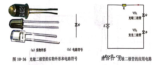 普通光敏二极管的检测
时间:2026-06-06
详细介绍8种常用的排序算法
时间:2026-06-06
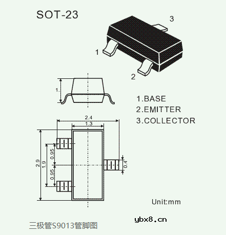 s9013三级管引脚图及参数
时间:2026-06-06
电压跟随器有什么作用?
时间:2026-06-06
VRRP是什么?VRRP的作用和工作原理
时间:2026-06-05
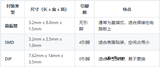 32768晶振封装尺寸详解
时间:2026-06-05
静态路由是什么?静态路由如何配置?
时间:2026-06-05
一文详解光耦的作用与分类、使用技巧
时间:2026-06-05
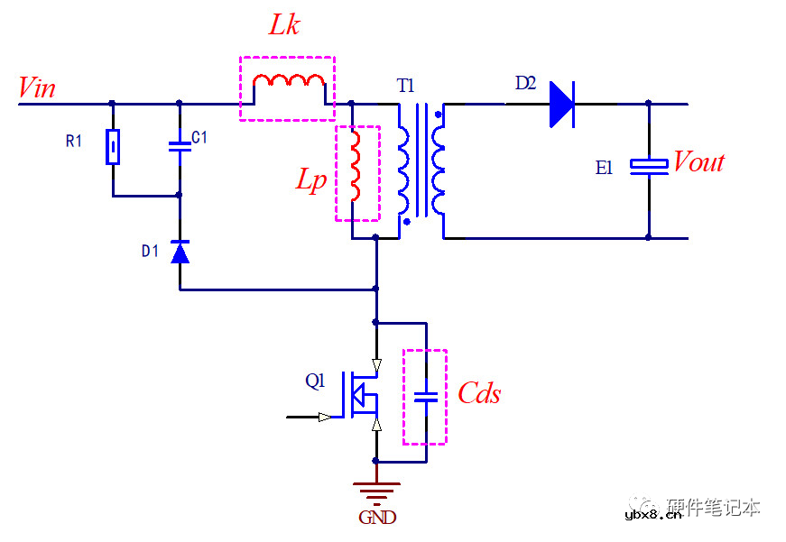 详解RCD钳位电路
时间:2026-03-08
三相异步电动机的拆装详讲
时间:2026-03-04
 基于逻辑门的构成解释如何完成任意逻辑的管...
时间:2026-03-08
三相异步电动机原理
时间:2026-03-04
 彩灯电路
彩灯电路
时间:2026-03-05
 NE555的有趣电路设计分享
时间:2026-03-08
 从0学电路,万用表演示测量三极管方法
时间:2026-03-08
 光耦在电子电路中作用、关键参数详解
时间:2026-03-08
 美的电磁炉电路图大全(六款美的电磁炉电路...
时间:2026-03-07
 H桥电机驱动电路解析
时间:2026-03-08